 International
 Singapore
 Malaysia
 Thailand
 Vietnam
Không có sản phẩm trong giỏ hàng!
*During write this tutorial, Xbee WiFi don’t have SoftAP mode yet. But now, Xbee WiFi offers SoftAP mode and much more suitable for this application. So it is recommended to read this tutorial: Remote Mobile Robot with XBee-WiFi (Android)
Since Digi International (company of XBee) has launch their WiFi module (XBee-WiFi), I am thinking to create a simple but interesting application using this module. What should be on your mind? Then I start to check my store, what should be the interested item. After a while I found this, mobile robot base with motor and wheel, MC40A board (I get this during the “spot 1 sen item” by Cytron), 7.4V LiPo Battery with connector, Xbee WiFi with SKXBee Rev2.0 and 4 set of PCB stands.
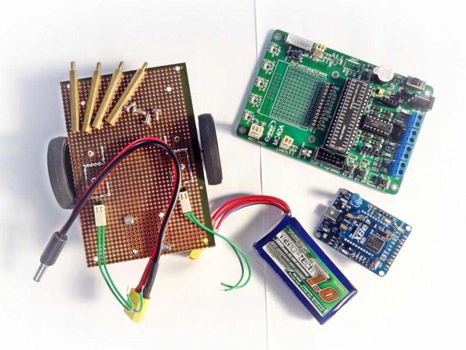
You can found all these item in Cytron Website:
1. Educational Mobile Robot 2.0 (EDUBOT2)
2. XBee WiFi Wire Antenna (XBEE-WIFI) *this item is not available in our store, you may find the replacemant.
3. XBee Starter Kit Without Module (SKXBEE BOARD), I am using SKXBee Rev2.0, if you are using Rev1.0, please refer here for minor modification.
4. 1 unit of 7.4V 900mAH LiPo Battery (LI-7.4-900)
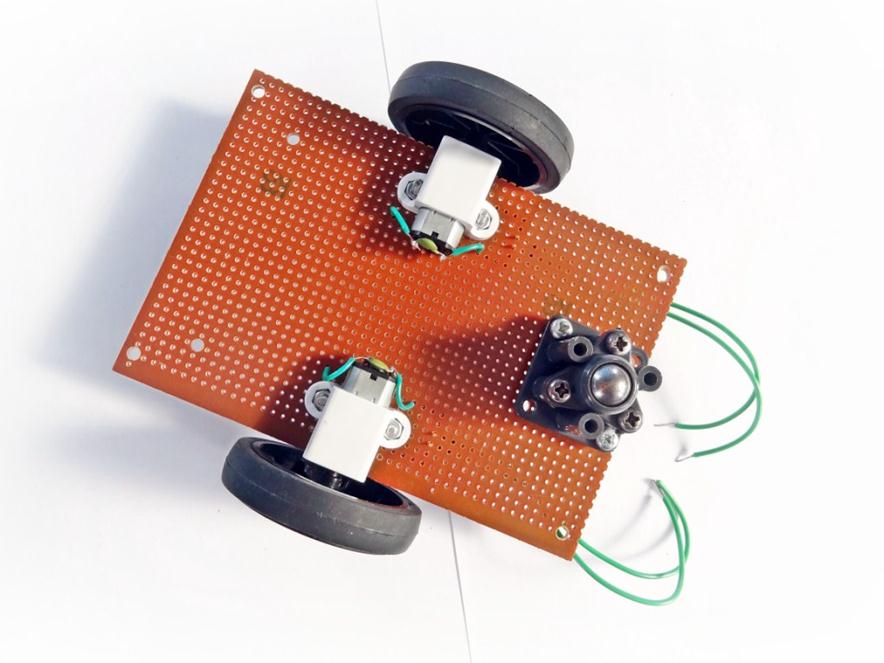
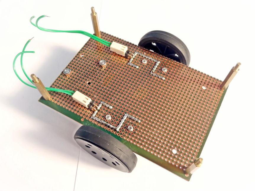
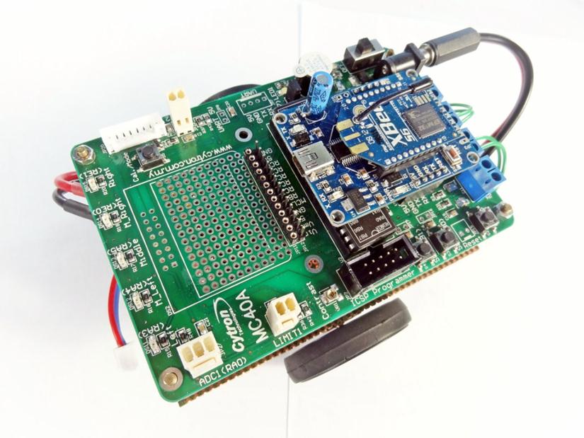
This is my base robot using donut board. I made it last 2 years, complete with SPG10 DC motors, extended bracket and Tamiya castor. At that time EDUBOT2is not launch yet, so I choose donut board as a base. Why? I can easily drill using Pro’sKIT mini hand drill.
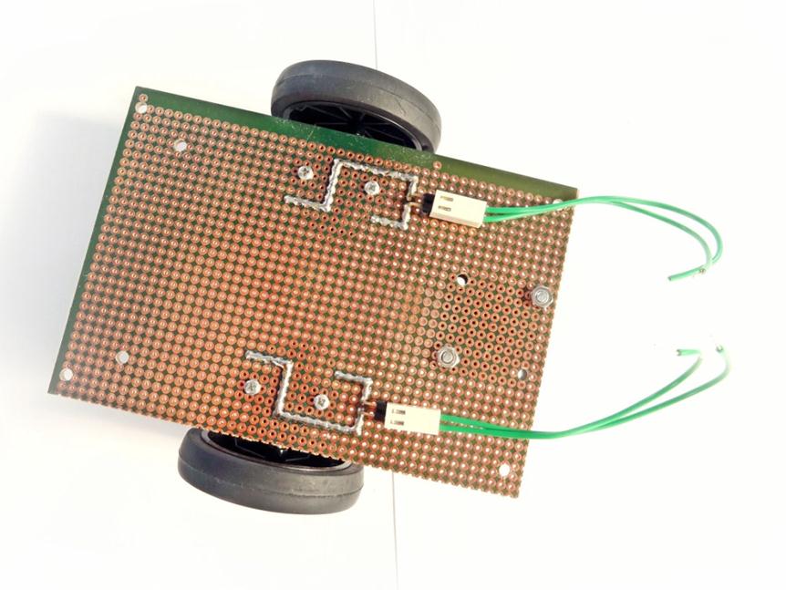
2 wires represent 2 point at each DC motor. It will be connected to MC40A ‘Left M’ and ‘Right M’ connector respectively. So I can control the DC motors direction.
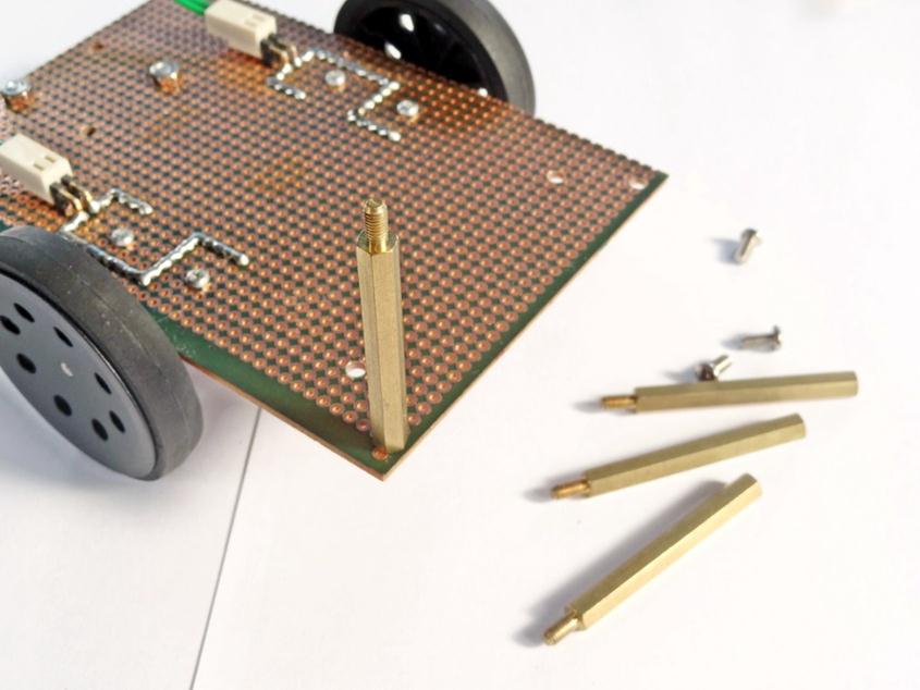
Time to start assemble the mobile robot. Put the PCB stands at every edge (hole) of base. Ok, done!
Wait, this PCB stands is too long, need to find a medium long PCB stands. Yes I have it. Ok, done! Look better, right?
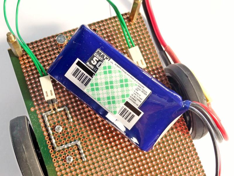
Next is battery, you utilize 2 unit of 3.7V 1100mAH LiIon Battery, or the easiest way to stick the battery at the base is by using the double sided tape.
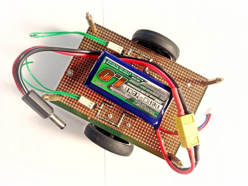
The wire converter for my battery is quite long. Need to manage the wire properly; at least it is not touching the wheel and the floor.
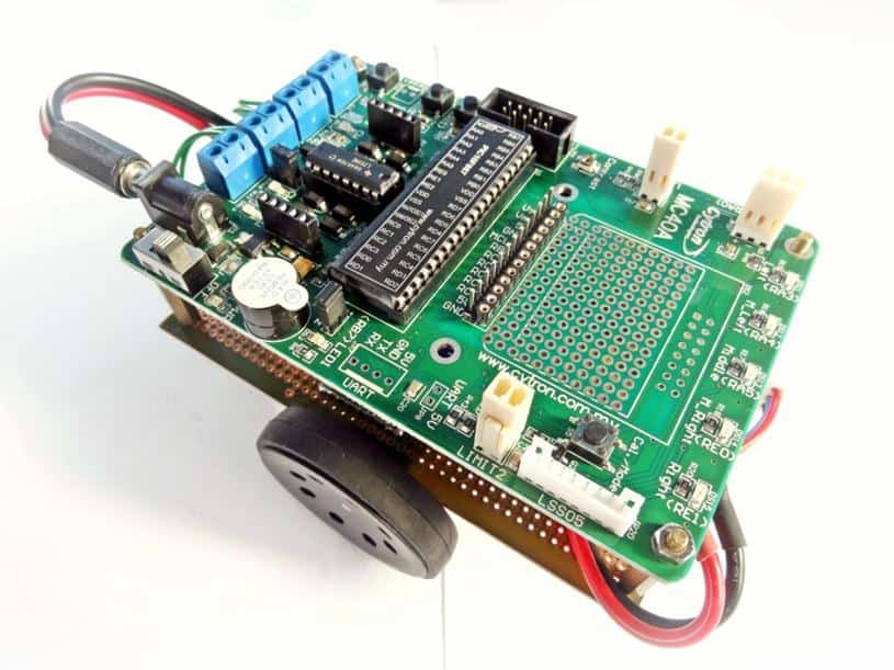
OK, mount the MC40A on the top, then put the nuts and screw it medium tight.
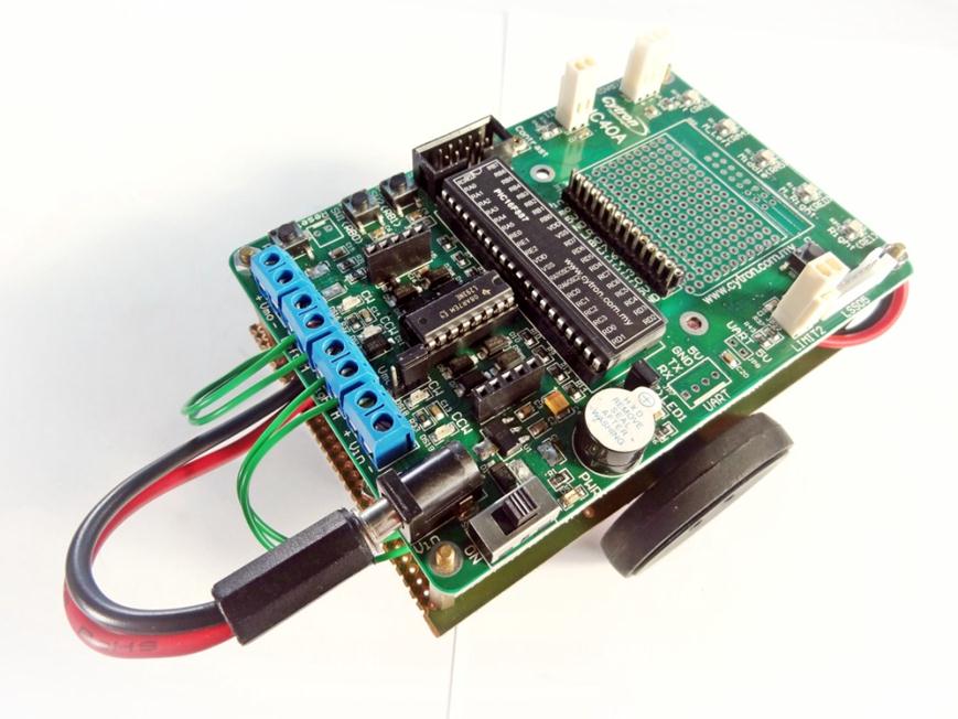
Connect all the wires respectively. Left motor connect to ‘Left M’ connector, right motor connect to ‘Right M’ connector and battery to Vin adapter. Set the mini jumper (Vmo/Vin) to Vin.
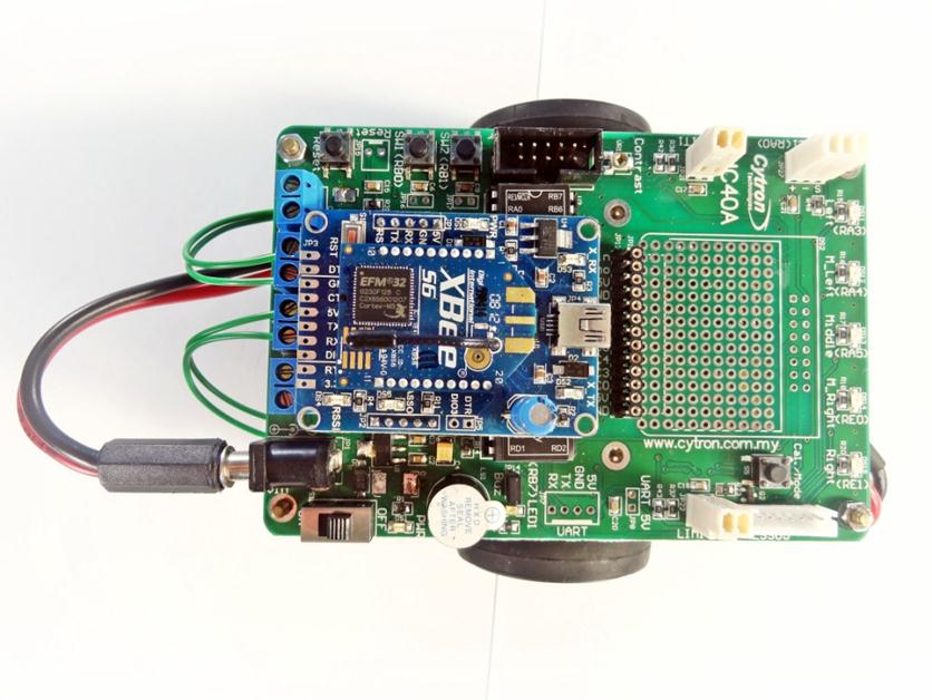
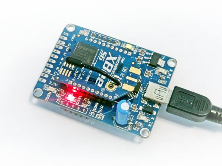
Finally put the XBee WiFi with SXBee (Rev2.0) on MC40A, there is a socket for it.
Ok, done with hardware. Very handsome right? Now time to set the XBee-WiFi.
I assume you know how to connect and open the XCTU software or you can refer to this tutorial “Getting Started with XBee-WiFi“.
Once your module has been recognized by the XCTU software, try to connect to your WiFi network. First click on ‘Active Scan > Scan’.
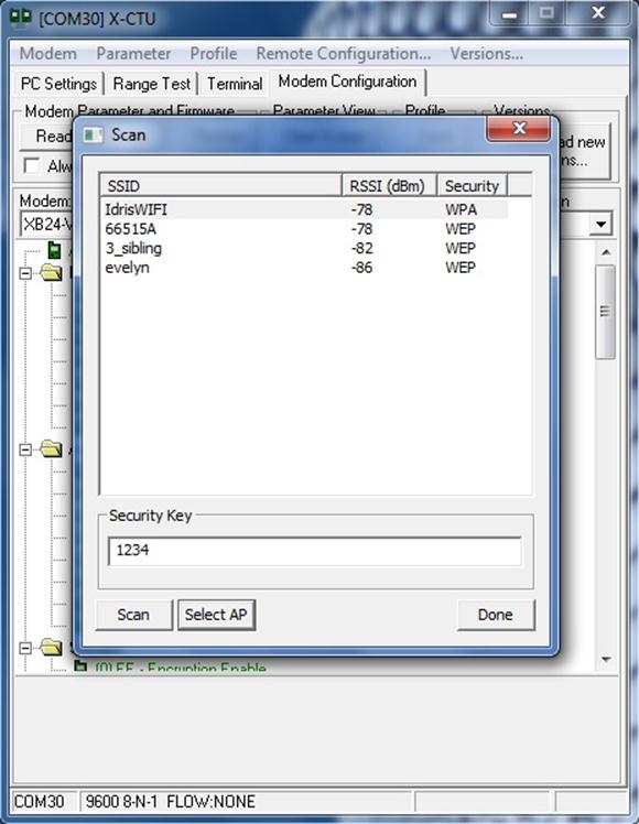
I’m using YES and this is my WiFi name “IdrisWiFi”. Click yours and enter the WiFi password.

Yes! My module connected to IdrisWiFi in 9614 ms.
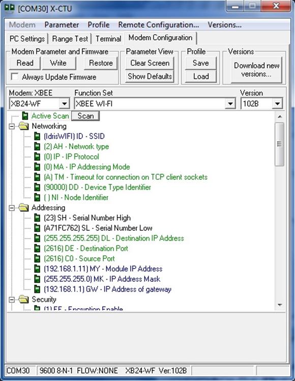
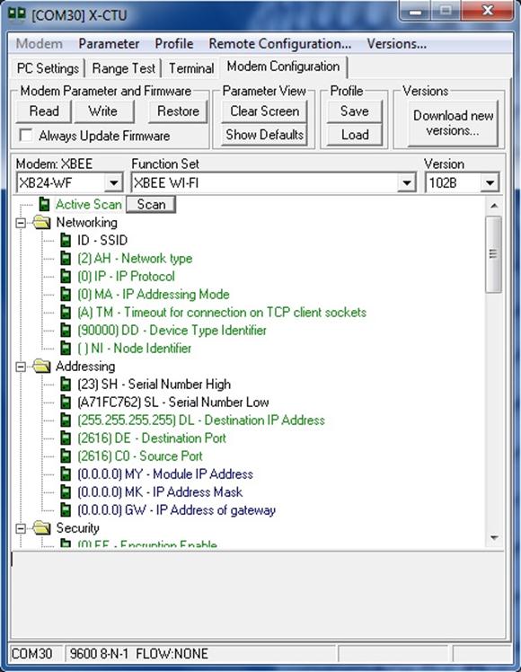
Once connected, ASSO LED (DS5) on your SKXbee will blink, that’s mean your module has successfully joined the WiFi network and it will be given specific IP address. Click on ‘Read’ and you will see the updated ‘MY – Module IP Address’, ‘MK – IP Address Mask’ and ‘GW – IP Address of Gateway’. Look at ‘DL – Destination IP Address’, it shows 255.255.255.255 which means the broadcast address. It is better to set it corresponding to your PC/laptop IP address.
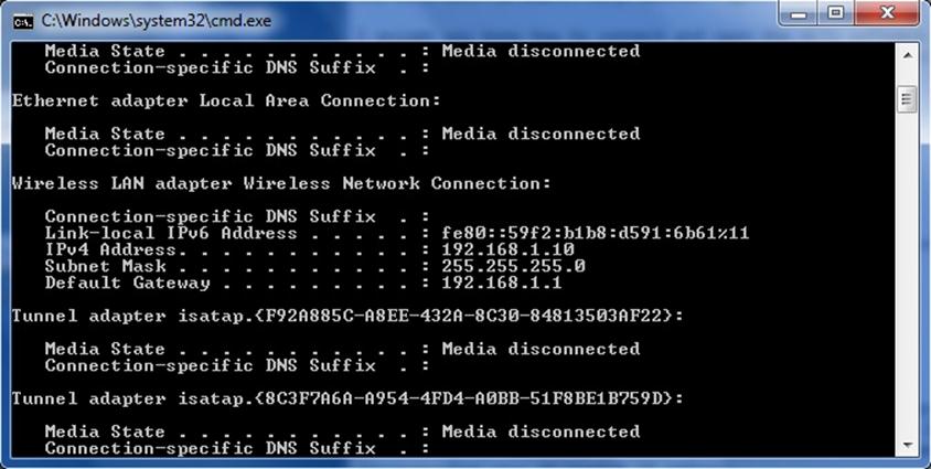
Make sure your PC/laptop connected to WiFi too. Then check your IP address. You can use command prompt, then type “ipconfig” followed by “enter”. It will display your current IP address. Mine is 192.168.1.10.
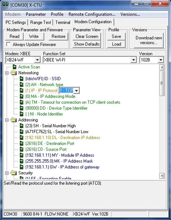
Now I will set the ‘DL – Destination IP Address’ to 192.168.1.10 in XCTU. Then change the ‘IP – IP Protocol’ to ‘1-TCP’. Why TCP? Because I just want to use the HyperTerminal software, and this software is a client TCP/IP. After done all the setting, click ‘Write’.
Make sure the ASSO LED (DS5) is blinking; otherwise you can press reset button on the SKXBee and wait until the ASSO LED is blink. Then click ‘Read’ again to double check all the parameter following what you set before. If it is different, you can repeat the configuration again.
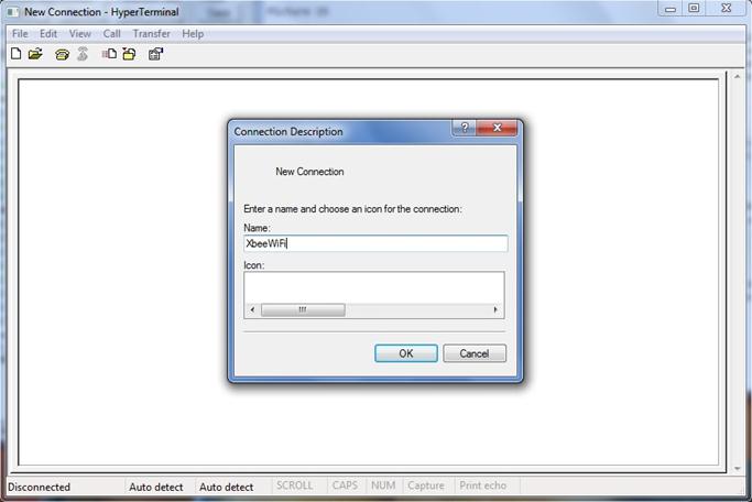
Now, I want to test the connection. Open HyperTerminal software, give a name e.g. “XbeeWiFi”.
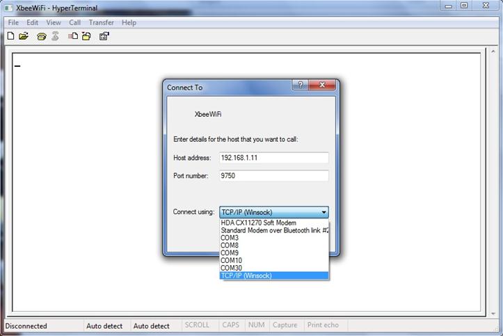
Choose connect using “TCP/IP (Winsock)”. Then type your module IP address at “Host address” box followed by “Port number”. Confuse?
“Host address” refers to ‘MY – Module IP Address’ (192.168.1.11)
“Port number” refers to ‘CO – Source Port’ (0x2616).
* REMEMBER! ‘CO – Source Port’ (XCTU) in HEX but “Port number” (HyperTerminal) in DEC.
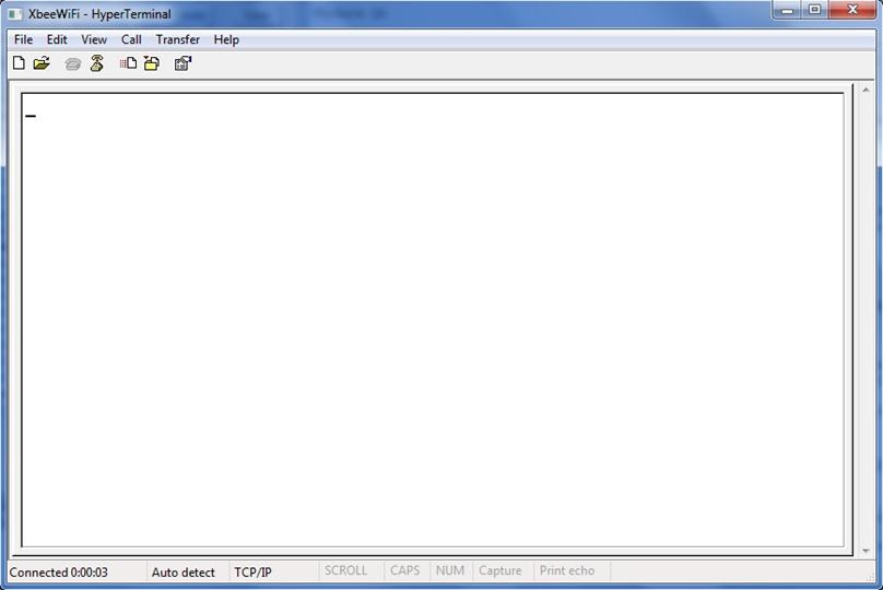
Click OK. Make sure it is Connected: 0.00.00 (look at bottom left).
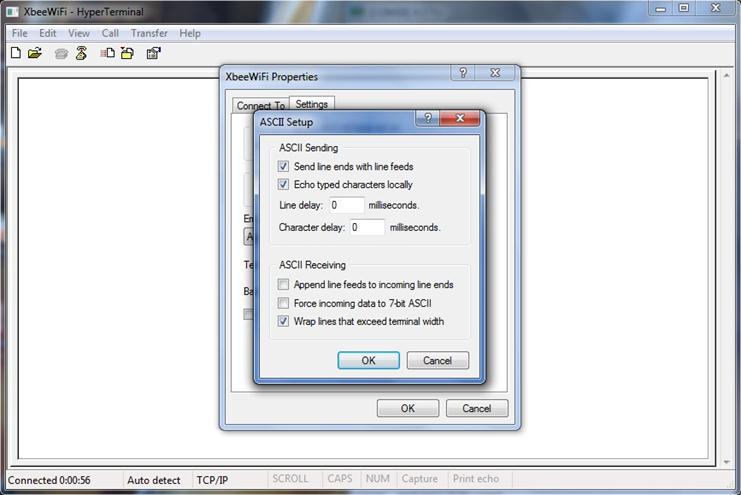
Don’t forget the basic setting on ASCII Setup. Check box for “Send line ends with line feed” and “Echo typed characters locally”.
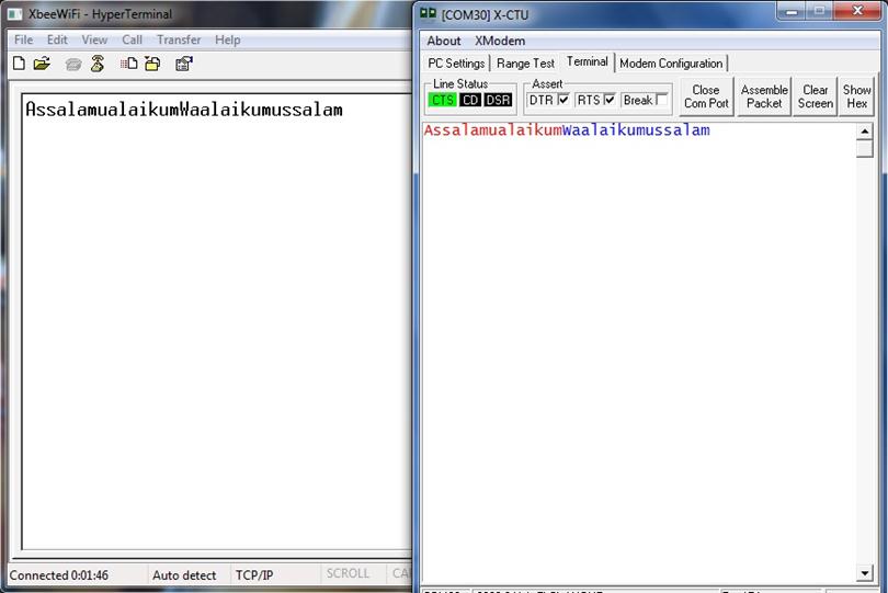
Try to send any data. “Assalamualaikum” is a data from HyperTerminal to XCTU, and “Waalaikumussalam” is a data from XCTU to HyperTerminal. The communication between my laptop and the module via WiFi network is success.
Now, time to program the PIC16F887. I’m using MPLAB X IDE V1.51 and XC8 V1.12. Let’s focus on the main part.
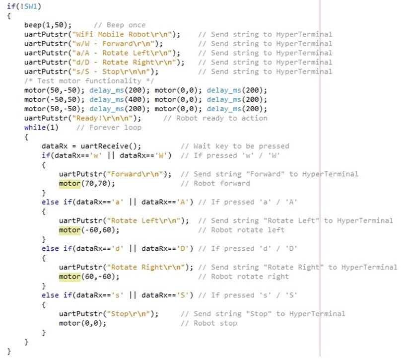
After you download the program, make sure the XBee-WiFi is connected to your laptop Wifi (check the ASSO LED on SKXBee Rev2.0, it should blink), press SW1. Robot will send some string to the HyperTerminal, then it will move a little left and right to test the motor. Once you get the “Ready!” string, you can start press a key on the keyboard.
w/W – Forward
a/A – Rotate Left
d/D – Rotate Right
s/S – Stop
That’s all from me, hope you can play with it. Of course you will face some problem and troubleshooting, that’s call experience, and experience gives you valuable knowledge.
P/S: If you have question for Author, please do discuss in Cytron’s technical forum.
[youtube]http://youtu.be/UQP6ay5ir_U[/youtube]
Sample Code: