 International
 Singapore
 Malaysia
 Thailand
 Vietnam
Không có sản phẩm trong giỏ hàng!

Rainbow Spark in Mini House using Maker Uno.
Introduction
Want to know how your house keep brighting using switch? Let us explore this project now by using Maker Uno !
Components needed :
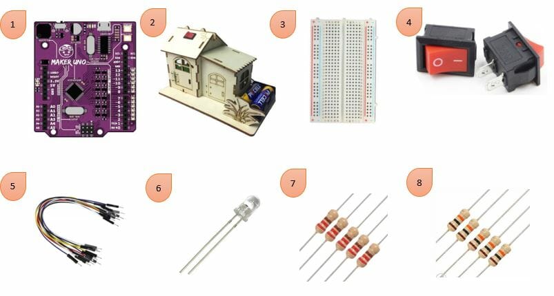
- Maker Uno
- House DIY Kit
- Mini Breadboard ( 8.5 x 5.5 cm, 400 holes)
- Rocker Switch Small 2 pins
- Male-to-Male Wire
- White LED
- Resistor (1 x 220 ohms)
- Resistor (1 x 10k ohms)
Steps
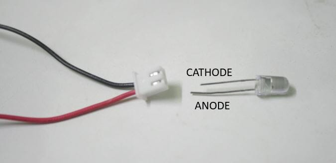
1. Anode(positive) of LED connected to the red wire. While cathode(negative) of LED connected to the black wire.
Note : To understand more on LED, click here.
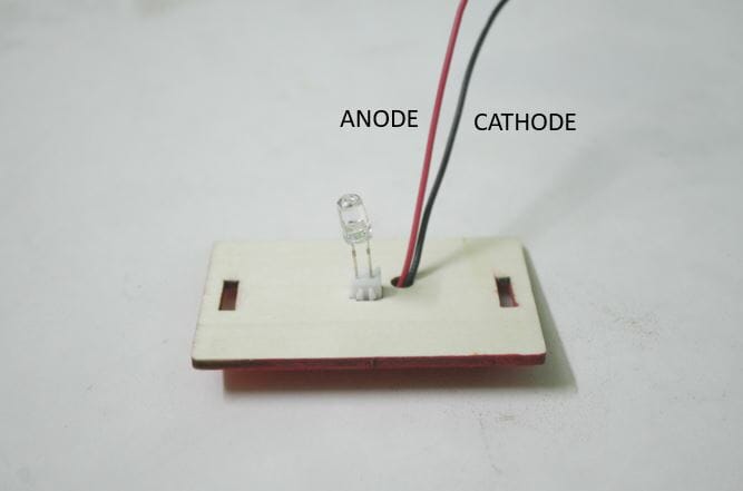
2. Put the LED into the slot of the house DIY kit.
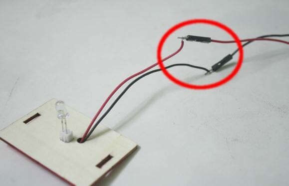
3. Stick the wire of LED with Male-to-Male wire using sellotape (like in the red circle).
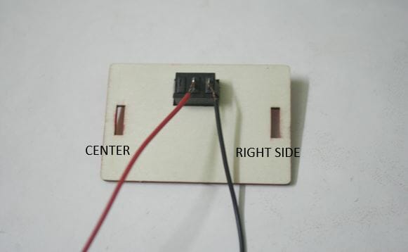
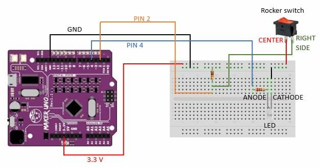
4. Connect the center and right side of the switch using different wires.
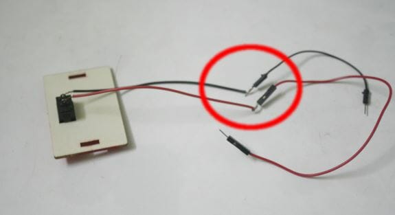
5. Stick the wire of Rocker Switch with Male-to-Male wire using sellotape (like in the red circle).
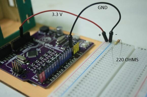
6. Pin 3.3 V connected to positive power rails(red side of breadboard) while pin GND connected to negative power rails(blue side of breadboard).
Put resistor 220 Ohms in terminal strips at different rows on each leg.
Note : To understand more on Breadboard, click here.
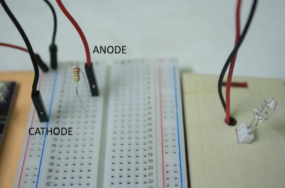
7. The Anode of the LED is connected at the same row of one leg resistor. The cathode of the LED is connected to negative power rails(blue side of breadboard).
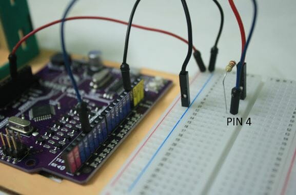
8. Connect the resistor to pin 4 of Maker Uno by put wire at the same row on terminal strips.
Note : To understand the Maker Uno Board, click here.
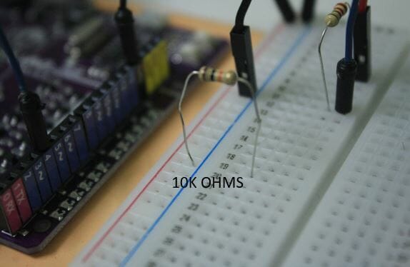
9. Resistor 10k Ohms was put on the breadboard. One leg of the resistor at terminal strips rows while another leg of the resistor at negative power rails.
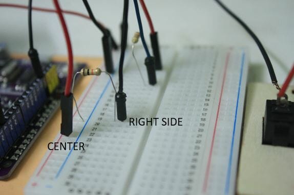
10. Wire from right side of switch is connected to the same rows of resistor while wire from center of switch is connected to positive power rails.
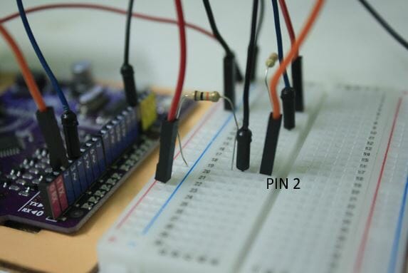
11. Connect a wire from same rows of resistor to pin 2 of Maker Uno.
Note : To understand the Maker Uno Board, click here.
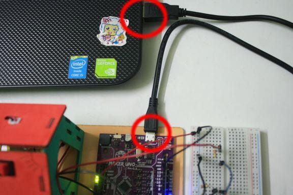
12. Connect Maker Uno and laptop/pc using USB (like in red circles).
13. Before proceed to this step, Arduino IDE have been installed and some setting is needed.
Note : Follow the step of installation and setup from this website.
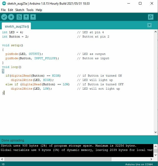
After done the installation, copy code from sample code section and paste into Arduino IDE.
To select the board model, go to Tools > Board > Arduino/Genuino Uno.
Click the “Upload” ![]() button to upload the sample code to your Maker UNO.
button to upload the sample code to your Maker UNO.
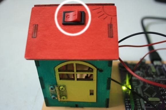
13. Switch (white circle) is turned OFF, LED not light up.
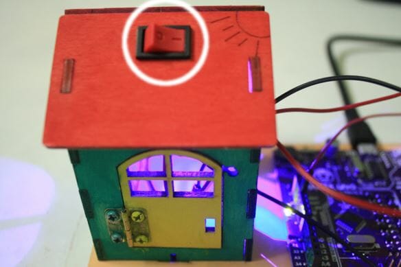
14. Switch (white circle) is turned ON, LED will light up.
Schematic Diagram
Video
Sample Code
int LED = 4;                              // LED at pin 4
int Button = 2;                           // Button at pin 2

void setup()
{
  pinMode(LED, OUTPUT);                   // LED as output
  pinMode(Button, INPUT_PULLUP);          // Button as input
}
void loop()
{
  if(digitalRead(Button) == HIGH)         // If Button is turned ON
     digitalWrite(LED, HIGH);             // LED will light up
  else if (digitalRead(Button) == LOW)    // If Button is turned OFF
     digitalWrite(LED, LOW);              // LED will not light up
}